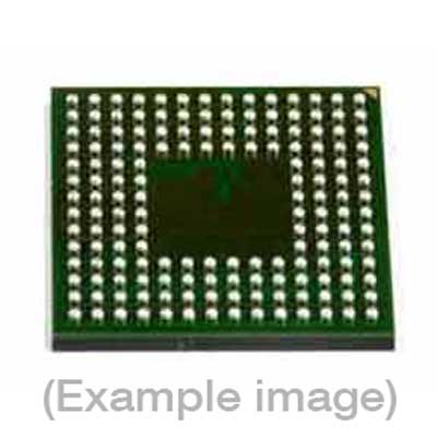
Adapters for Automated Programmers
| 9th Gen |
| FVE4ASM100LBGB, FVE4ASMR100LBGF |
Adapters for Manual Programmers
| 9th Gen |
| FVE4ASM100LBGB, FVE4ASMR100LBGF |
Adapters for Engineering Programmers
Last Updated: 05/18/2023
If the device is not yet supported by your BPM programmer (Generation), request Device Support
Note
IMPORTANT: This is a custom algorithm. Please see explanation at the bottom.
| Device Type: | eMMC |
| Device Size: | See below |
| Algorithm Programming Mode: | SDR |
Memory Organization:
| Memory Type |
Attributes*
|
Included in default Range (Y/N) | DUT Physical Byte Address (hex) | BPWin Buffer Byte Address (hex) |
| Boot Area Partition 1 | R/W/E | No | 0_0000_0000-0_07FF_FFFF | 0_0000_0000-0_07FF_FFFF |
| Boot Area Partition 2 | R/W/E | No | 0_0000_0000-0_07FF_FFFF | 0_0800_0000-0_0FFF_FFFF |
| User Data Area | R/W/E | Yes | 0_0000_0000-1_D1FF_FFFF | 0_1000_0000-1_E1FF_FFFF |
| Default Algorithm Range | — | — | 0_0000_0000-1_D1FF_FFFF | 0_1000_0000-1_E1FF_FFFF |
* R/W/E: readable and rewritable if not locked.Any configurations listed under ‘Device-Specific’ in the menu item Device-> Settings will be written to the DUT during ‘Program’ operation regardless of memory range selection.Special Device Considerations:
| 1. | Default Device Size: | 8 GByte |
| 2. | Device size after enhancing the full user area: | 3728 MByte |
| 3. | Total number of sectors: | 15269888 |
| 4. | Write Protect Group Size: | 8 MByte |
| 5. | High Capacity Write Protect Group Size: | 8 MByte |
| 6. | MAX_ENH_SIZE_MULT: | 1D2h |
| 7. | Serialization Supported: | No |
| 8. | RPMB partition is not currently supported by this algorithm. | |
| 9. | General Purpose Partitions 1-4 if any are mapped directly after the boot partitions. This is followed by the rest of the User Data Area. | |
| 10. | Sizes and attributes of General Purpose Partitions 1-4 can be set under Device->Settings. | |
| 11. | It is recommended to adjust the ‘High Device Address’ under Device->settings to match the end of the loaded data file(s). | |
| 12. | Each physical sector on the device has 512 bytes. | |
| 13. | If any partition is included in the erase operation that entire partition will be erased. | |
This is a custom algorithm that supports setting a user-defined boot partition size.In particular support for programming the vendor-specific BOOT_SIZE_MULT ECSD[127:125] values has been added.These can be set under Device->Settings and they will be programmed at the same time as the other partitioning settings.The PARTITION_SETTING_COMPLETED bit (ECSD[155] Bit 0) must be programmed to ‘1’ for this to take effect.All devices in an operation must have the same initial partition settings.Thus all devices should either have default partition settings or have been programmed to the same partition settings previously.The max partition size supported by the device is 128MB per boot partition. This corresponds to a setting of 000400h.This algorithm only supports up to 64MB boot partitions at this time. This corresponds to a setting of 000200h.This algorithm does not support disabling boot partitions by setting the BOOT_SIZE_MULT value to 000000h at this time.If increasing the boot partition size from the default 128KB it must be set to a value that is divisible by 512KB.The boot partition size is determined by multiplying the BOOT_SIZE_MULT by 128KB.This means that the BOOT_SIZE_MULT value must be divisible by 4 if increasing it from the default value of 000001h.Increasing the boot partition size will decrease the available sectors in the user data area.This algorithm will internally set the size of both the boot partitions and the user data area based on the ECSD read back during power on.Depending on your settings the full size allotted by the data buffer may not be usable. Please adjust your data file accordingly.The algorithm will skip operating on addresses that fall outside of the calculated boot partition or user data area size.For instance if using 16MB boot partitions only the first 16MB in the data buffer for each boot partition will be used.This does not apply to the Compare operation however. Any skipped areas must be set to all 00h values for Compare.The data buffer allots up to 128MB for each boot partition. Please make sure to use these offsets when loading data files.Data for boot partition 0 is mapped starting at data buffer address 0_0000_0000h.Data for boot partition 1 is mapped starting at data buffer address 0_0800_0000h.Data for the user data area and general purpose partitions is mapped starting at data buffer address 0_1000_0000h. ‘
BPM does not sell programmable devices, nor do we program devices directly. BPM makes programmers and accessories to make programming in-house fast, easy, and profitable.
Additional information
| 8-bit Bytes | 8086618112 |
|---|---|
| Manufacturer | Micron |
| Packages | BGA(100) |
| Part Number | MTFC8GACAEDQ-AIT |
| Set programming | Yes |
| Vcc(program) | 3.3 |
| Package |
