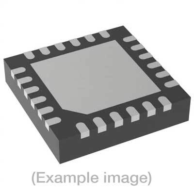
Adapters for Automated Programmers
| 8th Gen |
| FVE4ASMR32QNX, FVE4ASMR32QNX |
Adapters for Manual Programmers
| 8th Gen |
| FVE4ASMR32QNX, FVE4ASMR32QNX |
Adapters for Engineering Programmers
Last Updated: 05/18/2023
If the device is not yet supported by your BPM programmer (Generation), request Device Support
Note
IMPORTANT:
| Device Type: | ARM Cortex-M4 32-bit MCU |
| Device Size: | 256K-Byte Flash Memory |
| Algorithm Programming Method: | JTAG + Custom bootloader |
Memory Organization:
| Memory Type | Attributes* | Included inDefault Range | DUT Physical ByteAddress (hex) | BPWin Buffer ByteAddress (hex) |
| Main Flash Block | R/W/E | Yes | 0000_0000 – 0003_FFFF | 0000_0000 – 0003_FFFF |
| User Data Page | R/W/E | No | 0FE0_0000 – 0FE0_07FF | 0FE0_0000 – 0FE0_07FF |
| Lock Bits Page | R/W/E | No | 0FE0_4000 – 0FE0_47FF | 0FE0_4000 – 0FE0_47FF |
| Default Algorithm Range | — | — | 0000_0000 – 0003_FFFF | 0000_0000 – 0003_FFFF |
* R/W/E: readable and rewritable if not locked. Memory ranges can be selected under Device->Settings. Lock Bits Page:
| Memory Location | Lock Bit Name | Lock Bit Description |
| 0FE0_4000 | PLW[0] | There are 32 page lock bits per page lock word (PLW). Bit 0 refers to the first page and bit 31 refers to the last page within a PLW. |
| 0FE0_4004 | PLW[1] | There are 32 page lock bits per page lock word (PLW). Bit 0 refers to the 32nd page and bit 31 refers to the 63rd page within a PLW. |
| 0FE0_4xxx | PLW[N] | Thus PLW[0] contains lock bits for page 0-31 in the main block PLW[1] contains lock bits for page 32-63 etc.A page is locked when the bit is 0. A locked page cannot be erased or written. |
| 0FE0_41E8 | CLW | Word 122 is configuration word Zero. Bit[2] is the pinresetsoft bit. Bit[1] is the bootloader enable bit. |
| 0FE0_41F0 | ALW | Word 124 is the Authentication Access Port (AAP) lock word (ALW) and the four LSBs of this word are the lock bits.If these bits are 0xF then AAP access is enabled.Locking AAP is irreversible. Once AAP is locked it will be impossible to perform an external mass erase and AAP lock cannot be reset. |
| 0FE0_41F4 | MLW | Word 125 is the mass erase lock word (MLW). Bit 0 locks the entire flash. The mass erase lock bits willnot have any effect on device erases initiated from the Authenitcation Access Port (AAP) registers. |
| 0FE0_41F8 | ULW | Word 126 is the user page lock word (ULW). Bit 0 of this word is the User Data Page lock bit. Bit 1 in this word locks the Lock Bits Page. |
| 0FE0_41FC | DLW | Word 127 is the debug lock word (DLW). The four LSBs of this word are the debug lock bits. If these bits are 0xFthen debug access is enabled.Locking debug access will disable access to the device by the programmer. |
BPM does not sell programmable devices, nor do we program devices directly. BPM makes programmers and accessories to make programming in-house fast, easy, and profitable.
Additional information
| 8-bit Bytes | 266356736 |
|---|---|
| Manufacturer | Silicon Laboratories |
| Packages | QFN(32) |
| Part Number | EFR32MG1V132F256IM32-B0R |
| Set programming | Yes |
| Vcc(program) | 3.3 |
| Package |
