Not all programming solutions are the same. If quality and maximum device life are important, it’s imperative to know what to look for. When evaluating a programming solution, ask about signal integrity. Review this white paper for helpful tips.
35 Years of NAND Flash Memory
35 Years of NAND Flash Memory
2022 marks the 35th anniversary of the invention of NAND flash memory. NOR Flash memory was invented by Dr. Fujio Masuoka while working for Toshiba in 1984. NOR-based flash has long erase and write times but has a full address/data (memory) interface that allows random access to any location. This makes it suitable for the storage of program code that needs to be infrequently updated, such as a computer’s BIOS or the firmware of set-top boxes. Its endurance is 10,000 to 1,000,000 erase cycles. NOR-based flash was the basis of early flash-based removable media; Compact Flash was originally based on it, though later cards moved to the cheaper NAND flash.
NAND flash was born out of a joint venture with Samsung and Toshiba and followed shortly thereafter. It has faster erase and write times, higher density, lower cost per bit than NOR flash, and ten times the endurance. However, it is most suitable for mass-storage devices such as PC cards and various memory cards because of its sequential write and is less useful for computer memory.
BPM has been around slightly longer than NAND Flash and has developed solutions for some of the particular challenges of programming flash devices. See the Flash white papers below.
KIOXIA Celebrates the 35th Anniversary of Invention of NAND Flash Memory

SAN JOSE, Calif., February 10, 2022 – What do the MP3 players of the 1990s and today’s smartphones have in common? Neither would exist were it not for NAND flash memory, an innovation whose influence has reverberated throughout the decades. KIOXIA America, Inc. today announced that it has reached a new milestone – 2022 marks the 35th anniversary of the company’s invention of NAND flash memory.
NAND Flash Video
A new humorous video series from KIOXIA, that explores life without flash memory, kicks off with a look at cloud computing
Flash Memory White Papers
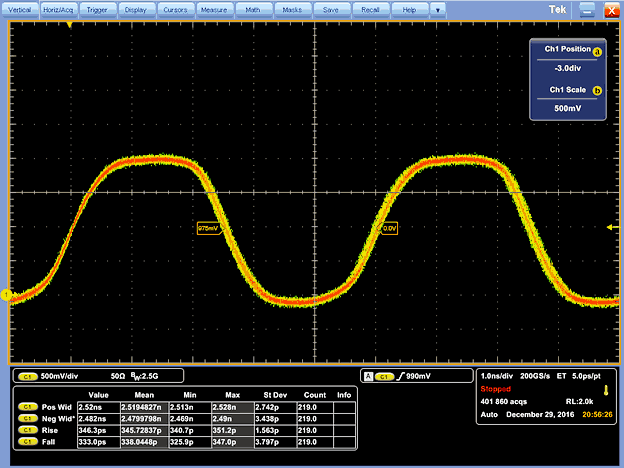
Signal Integrity
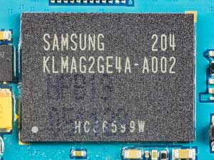
Mastering eMMC Device Programming
Over the past decade, the demand for high-density, nonvolatile memories with a small footprint has increased dramatically. Two of the most popular markets driving this demand are handheld devices and automotive. Demand for handheld devices continues to drive the research for high-density, low power, low-cost, high-speed, nonvolatile memories while maintaining a small footprint. NAND-type flash memory is the perfect match for such a market. The increased consumer demand for high-tech features in automobiles, such as infotainment systems, is also a big driver of demand for high-density NAND-based devices.
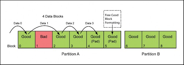
Understanding NAND Flash Factory Programming
During the manufacturing of electronic systems, blank non-volatile devices must often be programmed with initial data content. This allows the target system to get up and running, and is referred to as “factory programming,” “factory pre-programming,” or “bulk programming.” Generally, this is a very straightforward process that has been in place in the industry for many years. However, with NAND flash the process is more difficult.
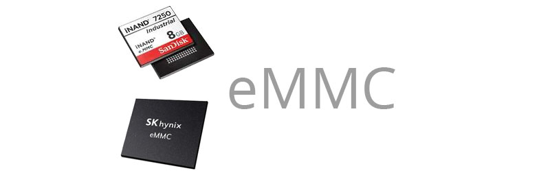
 BPM Microsystems is pleased to announce new device support for SanDisk and Hynix eMMC devices with significantly faster HS400 protocol
 Hynix Semiconductor H26M41208HPRQ
 BPM Advantages
 Each part you are programming was tested and qualified on a “million-dollar” tester at the Semi House to ensure it works correctly. The device manufacturer guarantees the part will work if you meet the parts specifications. They do not test the part to ensure it will work with overshoot, ringing, ground bounce, VCC noise, ground noise, crosstalk, substrate noise, low edge rates, no bypass capacitor, setup violations, hold time violations, shorter than required programming pulses and other signal integrity problems.